2 Jet Nozzle Flow
2.1 Hydraulic Impact Force
In the drilling industry we usually assume that the jet will impact the hole bottom without loss of momentum [7] and, sometimes, can be wrongly interpreted (mainly when we have a big clearance between the bit attack area and the bottom of the well) as having the same velocity profile hitting the bottom. Lets us take the most used formula to calculate the hydraulic impact force in pounds:
(1) Fj = 0.01823Cdq√(ρΔpb)
Where Cdis a discharge coefficient that ranges between 0.95 and 1.03; q is the flow rate in gpm; ρ, the fluid density in pounds per gallon and Δpbis pressure drop across the bit in psi. Having this in mind and taking into consideration an usual drilling parameters regarding hydraulics we have the following:
| TFA | Cd | q | ρ | Δpb | Fj |
| 0.969 in² | 0.95 | 600 gpm | 9.6 ppg | 338.9 psi | 592.7 lbf |
| 625.16 mm² | 0.95 | 2271.25 lpm | 1.15 g/cm³ | 2.3366 MPa | 2636.46 N |
Proceeding with a simple math, following the assumption that the jet won’t spread out before hitting the bottom and every jet (doesn’t matter its diameter) will keep the same impinging velocity, we have a hydraulic impact pressure value of 611 psi ( 4.2127 MPa ) for each nozzle.
2.2 Spreading Out the Jet and Cavitating Clouds
It is going to be seen that the flow of submerged jets are well known [8] and posses some distinct regions (4↓):

From (4↑) is possible to see that when the jet exits the nozzle, the velocity gradient creates shearing at the edges which transfers momentum. Taking into account this process we can easily visualize the jet dissipates energy and the velocity profile is widened.
Sato et al [9] carried out experiments where they had a submerged jet nozzle and they used these experiments to investigate the occurrence of cavitating clouds where they saw a ring-like erosion distribution over an acrylic plate that could be related to cavitation on impinging walls. Hutli [10]concluded through experiments that the cavitation exhibits a regular frequency of oscillation. It is known that cavitation in a well can occur on very shallow depths, but when we are deep is quite difficult its appearance. The key behind bringing this subject is the already mentioned statement "cavitation exhibits a regular frequency of oscillation", so, if cavitation happens on submerged nozzles in above mentioned experiments, the occurrence of low pressure zones in deep wells are possible and they are cyclic.
3 CFD Simulation
Having this background, and in order to capture these low pressure zones, were simulated the same boundary geometry (5↓) and three different nozzle diameters having a high density of nodes at the shear layer: 10/32" (7↓), 12/32" (8↓) and 14/32" (9↓) with 60 m/s (196.85 ft/s) of jet velocity with the same drilling fluid parameters ( MW= 9.6 ppg, YP= 27 cP, PV=22cP). The difference of hidrostactic pressure between the inlet of the nozzle and the bottom of the hole is negligible when compared with the impinging pressure.
The simulation was carried out using Openfoam on a Debian based computer with a transient PISO algorithm. Each run took 24 hours to be solved.


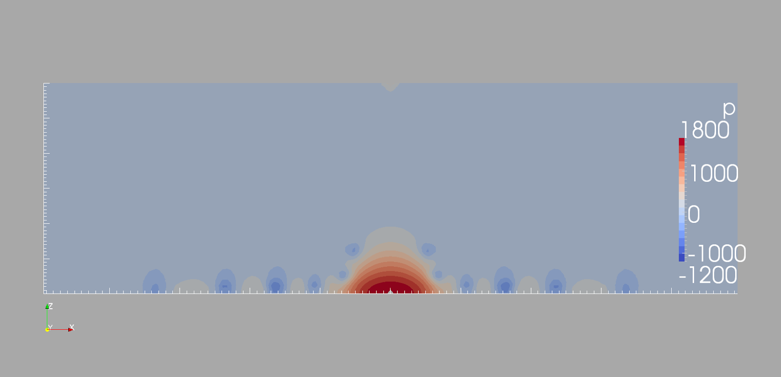
We can see that the jet velocity (7↓,8↓,9↓), just before hitting the bottom of the well, is no longer the same as the nozzle exit and just at the impingement area we can see a stagnation region.


Figure 9 Velocity profile for 14/32" Nozzle with average exit velocity of 60 m/s (196.85 ft/s) after reaching fully developed flow.
The simulations regarding the pressure profiles gave us some very good results. The PISO algorithm uses the kinematic viscosity to solve the Navier Stokes equations, so, the results are the rho-normalized pressure with units in (m²/s²). For the case of this used drilling fluid we should expect values close to 2031 m²/s². We can see in ( 10↓, 11↓, 12↓ ) that the values are quite close to the expected value. In fact they are smaller, this is because in the Fj equation is not assumed we have energy losses between the jet and the surrounding fluid.


References
[1] Carlos H.L. Bruhn, José Adilson T. Gomes, Cesar Del Lucchese Jr., and Paulo R.S Johann – “Campos Basin: Reservoir Characterization and Management – Historical Overview and Future Challenges”, OTC 15220, 2003.
[2] Bernardo, R.J, Saliés, J.B., and Polilo Filho, A.: “Campos Basin: Lessons Learned and Critical Issues to be Overcome in Drilling and Completion Operations”, OTC 15221, 2003.
[3] B. S. McLaury, S. A. Shirazi, Q. H. Mazumder, V. Viswanathan – “Effect of Upstream Pipe Orientation on Erosion in Bends for Annular Flow”
[4] Bill Chemerinski, SPE , Imperial Oil Resources, Ltd. and Leon Robinson, SPE, OGCI – “Hydraulic Wellbore Erosion While Drilling”
[5] Zeidler. H. Udo, Oyez Business Seminar, Innovations in Bit Technology, Oct. 9.1981, Houston. Texas – “Hydraulics and Hole Erosion”
[6] Steve Barton, Kirk Card, and Garrett Pierce, NOV Downhole – “Delivering Steering Success in Problematic Soft Formation Directional Wells”
[7] A. T. Burgoyne Jr., K. K. Milheim, M. E. Chevernet, F.S. Young Jr. - "Applied Drilling Engineering"
[8] N. Zuckerman and N. Lior - "Jet Impingement Heat Transfer: Physics, Correlations, and Numerical Modeling"
[9] K. Sato, Y. Sugimoto and S.Ohjimi - "Pressure-Wave Formation and Collapses of Cavitation Clouds Impinging on Solid Wall in a Submerged Water Jet"
[10] E. A. F. Hutli and M. S. Nedeljkovic - "Investigation of a Submerged Cavitating Jet Behavior: Part One - The Phenomenon, Detection Technique and Sono-Luminescence"
Nenhum comentário:
Postar um comentário