domingo, 14 de abril de 2013

Exercise - Moineau Rotor

My idea is only to take the skills we got from working with stabilizer and apply on another creation. A Moineau Based Design Rotor and for that we have 2 approaches: Salomé Gui or Salomé Python Script.

As you should know this rotor is part of what we call PCP's (Progressive Cavity Pumps) and they are used in several areas in the industry. In my area, oil well drilling, they are part of what we call, drilling motors. Google it!!

The rotor it self has two types of geometries designs:

  1. Cross-sectional 
  2. Axial 
Cross-Sectional 

Its cross-sectional design is ruled by the hypocycloid. If the inner rolling circle has diameter ratio of 6:1 related to the outer circle, the rotor will have 6 lobes.


Example of a hypocycloid taken from http://images.yourdictionary.com/hypocycloid


Axial

Its axial geometry is going to look like a helix and can be solely defined by pitch length.

A Dyna-Drill drilling motor model inside of its stator.

I will take an example from the specs inside the following link: http://www.cougards.com/wp-content/uploads/_pdfs/Motor%20Operations%20Handbook%202012.pdf

Usually the manufacturers are not going to release the amount of rubber coverage is inside of a stator. I've never did a motor maintenance ... so, we must "engineering" assume some of the values. In other words, we must guess.

From the specs, comes the following picture

Some measurements from a drilling motor

We want the value related to the rotor's length. It should be "H"-"F". To have a value we must pick one motor. I choose a 8" 7-8 4.0 drilling motor. The power section's length should be approximately 5.8 m. The rotor's I must "engineering" guess that would be 6.5". From the specs we know the pitch in this power section will be 4.0 divided by 5.8m and the rotor will have 7 lobes. We have all the values right now!!

We can begin.

I'll post the solution on the next post.


Creating a spiral drilling stabilizer with Salomé - Python Script

As I promised, we are going to take a look at the Python script generated by the dump file from the generated stabilizer. But ... to make things clear ... I'm not an expert on Python but I try to make things to be reusable as much as possible. My coding can be very ugly, but I understand them on the first sight.

I would suggest you to visit the following links regarding Salomé's script:

I know this can be boring but that is why I strongly suggest you to have a problem to be solved, a driver ... something to give you a purpose, and if do so learn something from the script, it can save you lots and lots of time.


Time to go.


  1. Open Salomé and load the hdf file you had created. 
  2. Press "Ctrl" + "D" or go to "File >> Dump Study". 
  3. Name your python file the way you would like.
  4. Save it.
The generated file:

  1. # -*- coding: iso-8859-1 -*-

  2. ###
  3. ### This file is generated automatically by SALOME v6.6.0 with dump python functionality
  4. ###

  5. import sys
  6. import salome

  7. salome.salome_init()
  8. theStudy = salome.myStudy

  9. import salome_notebook
  10. notebook = salome_notebook.notebook
  11. sys.path.insert( 0, r'/media/rafael/5e8dda66-24fd-42c8-b0d6-ece1a49fa89d/Projects/CFD/Salome')

  12. ###
  13. ### GEOM component
  14. ###

  15. import GEOM
  16. import geompy
  17. import math
  18. import SALOMEDS


  19. geompy.init_geom(theStudy)

  20. O = geompy.MakeVertex(0, 0, 0)
  21. OX = geompy.MakeVectorDXDYDZ(1, 0, 0)
  22. OY = geompy.MakeVectorDXDYDZ(0, 1, 0)
  23. OZ = geompy.MakeVectorDXDYDZ(0, 0, 1)
  24. OD_max_point = geompy.MakeVertexWithRef(O, 0.10795, 0, 0)
  25. Vertex_1 = geompy.MakeVertexWithRef(OD_max_point, 0, 0.3, 0)
  26. OD_min_point = geompy.MakeVertexWithRef(Vertex_1, -0.0254, 0.043994, 0)
  27. Vertex_2 = geompy.MakeVertexWithRef(OD_min_point, 0, 0.6, 0)
  28. Vertex_3 = geompy.MakeVertex(0, 0.943994, 0)
  29. Line_1 = geompy.MakeLineTwoPnt(Vertex_3, O)
  30. Line_2 = geompy.MakeLineTwoPnt(O, OD_max_point)
  31. Line_3 = geompy.MakeLineTwoPnt(OD_max_point, Vertex_1)
  32. Line_4 = geompy.MakeLineTwoPnt(Vertex_1, OD_min_point)
  33. Line_5 = geompy.MakeLineTwoPnt(OD_min_point, Vertex_2)
  34. Line_1_vertex_2 = geompy.GetSubShape(Line_1, [2])
  35. Line_6 = geompy.MakeLineTwoPnt(Vertex_2, Line_1_vertex_2)
  36. Wire_1 = geompy.MakeWire([Line_1, Line_2, Line_3, Line_4, Line_5, Line_6], 1e-07)
  37. Face_1 = geompy.MakeFaceWires([Wire_1], 1)
  38. Revolution_1 = geompy.MakeRevolution(Face_1, OY, 360*math.pi/180.0)
  39. geomObj_1 = geompy.MakeCurveParametric("0.5*0.2159*cos(t+pi/2)", "t*1.2/pi", "0.5*0.2159*sin(t+pi/2)", 0, 1, 999, geompy.GEOM.Interpolation, True)
  40. [geomObj_2,geomObj_3] = geompy.ExtractShapes(geomObj_1, geompy.ShapeType["VERTEX"], True)
  41. geomObj_4 = geompy.MakeCurveParametric("0.5*0.1651*cos(t+pi/2)", "t*1.2/pi", "0.5*0.1651*sin(t+pi/2)", 0, 1, 999, geompy.GEOM.Interpolation, True)
  42. [geomObj_5,geomObj_6] = geompy.ExtractShapes(geomObj_4, geompy.ShapeType["VERTEX"], True)
  43. geomObj_7 = geompy.MakeEdge(geomObj_2, geomObj_5)
  44. geomObj_8 = geompy.MakeEdge(geomObj_6, geomObj_3)
  45. geomObj_9 = geompy.MakeWire([geomObj_1, geomObj_4, geomObj_7, geomObj_8], 1e-07)
  46. geomObj_10 = geompy.MakeFaceWires([geomObj_9], 0)
  47. geomObj_11 = geompy.MakeRevolution(geomObj_10, OY, 40*math.pi/180.0)
  48. Curve_1 = geompy.MakeCurveParametric("0.6*0.2159*cos(t+pi/2)", "t*1.2/pi", "0.6*0.2159*sin(t+pi/2)", 0, 0.9, 999, geompy.GEOM.Interpolation, True)
  49. [Vertex_4,Vertex_5] = geompy.ExtractShapes(Curve_1, geompy.ShapeType["VERTEX"], True)
  50. Curve_2 = geompy.MakeCurveParametric("0.5*0.1651*cos(t+pi/2)", "t*1.2/pi", "0.5*0.1651*sin(t+pi/2)", 0, 0.9, 999, geompy.GEOM.Interpolation, True)
  51. [Vertex_6,Vertex_7] = geompy.ExtractShapes(Curve_2, geompy.ShapeType["VERTEX"], True)
  52. Edge_1 = geompy.MakeEdge(Vertex_4, Vertex_6)
  53. Edge_2 = geompy.MakeEdge(Vertex_7, Vertex_5)
  54. Wire_2 = geompy.MakeWire([Curve_1, Curve_2, Edge_1, Edge_2], 1e-07)
  55. Face_2 = geompy.MakeFaceWires([Wire_2], 0)
  56. Revolution_2 = geompy.MakeRevolution(Face_2, OY, 80*math.pi/180.0)
  57. Cut_1 = geompy.MakeCut(Revolution_1, Revolution_2)
  58. geompy.Rotate(Cut_1, OY, 120*math.pi/180.0)
  59. Cut_2 = geompy.MakeCut(Cut_1, Revolution_2)
  60. geompy.Rotate(Cut_2, OY, 120*math.pi/180.0)
  61. Cut_3 = geompy.MakeCut(Cut_2, Revolution_2)
  62. Mirror_1 = geompy.MakeMirrorByAxis(Cut_3, OX)
  63. geompy.Rotate(Mirror_1, OY, 20*math.pi/180.0)
  64. Fuse_1 = geompy.MakeFuse(Cut_3, Mirror_1)
  65. geompy.addToStudy( O, 'O' )
  66. geompy.addToStudy( OX, 'OX' )
  67. geompy.addToStudy( OY, 'OY' )
  68. geompy.addToStudy( OZ, 'OZ' )
  69. geompy.addToStudy( OD_max_point, 'OD_max_point' )
  70. geompy.addToStudy( Vertex_1, 'Vertex_1' )
  71. geompy.addToStudy( OD_min_point, 'OD_min_point' )
  72. geompy.addToStudy( Vertex_2, 'Vertex_2' )
  73. geompy.addToStudy( Vertex_3, 'Vertex_3' )
  74. geompy.addToStudy( Line_1, 'Line_1' )
  75. geompy.addToStudy( Line_2, 'Line_2' )
  76. geompy.addToStudy( Line_3, 'Line_3' )
  77. geompy.addToStudy( Line_4, 'Line_4' )
  78. geompy.addToStudy( Line_5, 'Line_5' )
  79. geompy.addToStudyInFather( Line_1, Line_1_vertex_2, 'Line_1:vertex_2' )
  80. geompy.addToStudy( Line_6, 'Line_6' )
  81. geompy.addToStudy( Wire_1, 'Wire_1' )
  82. geompy.addToStudy( Face_1, 'Face_1' )
  83. geompy.addToStudy( Revolution_1, 'Revolution_1' )
  84. geompy.addToStudy( Curve_1, 'Curve_1' )
  85. geompy.addToStudy( Curve_2, 'Curve_2' )
  86. geompy.addToStudyInFather( Curve_1, Vertex_4, 'Vertex_4' )
  87. geompy.addToStudyInFather( Curve_1, Vertex_5, 'Vertex_5' )
  88. geompy.addToStudyInFather( Curve_2, Vertex_6, 'Vertex_6' )
  89. geompy.addToStudyInFather( Curve_2, Vertex_7, 'Vertex_7' )
  90. geompy.addToStudy( Edge_1, 'Edge_1' )
  91. geompy.addToStudy( Edge_2, 'Edge_2' )
  92. geompy.addToStudy( Wire_2, 'Wire_2' )
  93. geompy.addToStudy( Face_2, 'Face_2' )
  94. geompy.addToStudy( Revolution_2, 'Revolution_2' )
  95. geompy.addToStudy( Cut_1, 'Cut_1' )
  96. geompy.addToStudy( Cut_2, 'Cut_2' )
  97. geompy.addToStudy( Mirror_1, 'Mirror_1' )
  98. geompy.addToStudy( Cut_3, 'Cut_3' )
  99. geompy.addToStudy( Fuse_1, 'Fuse_1' )
Just ugly ... I used to get terrified by coding but, as I mentioned ... you'll save time. You can take this time and enjoy in a nerdish way by improving the code, or the tool, I don't know ... just choose something. 

I would like to explain from the line 1 to 28, but I'm here to be practical so, don't touch them. 

Why do we need to take a look on this? Well, mainly because I would like to understand what is happening and also, because, we can draw any type of stabilizer. But, as heads up, If you want to create any sort of STB you probably are going to debug the code or create more code. Why? A Spiral STB is a tortuous tool and it depends on the precision ... sometimes the cutting action over the virgin tool, won't work, that is when you need to debug the code/design.

From now on I'll try to comment the coding.

29 - From the previous Salomé, I believe, we had to create the origin point. Salomé 6.6 takes care of this by creating the O vertex at (0,0,0). That is what this line of code does, calls the geompy package and asks for MakeVertex function.

30-32 - From these lines is possible to observe that it was created the unit vectors by calling the MakeVector function. Again, this a good thing and shouldn't be touched.

33-36 - As we did with the first steps with stabilizer creation. We used a reference to create our vertexes . The MakeVertexWithRef function asks for the Reference point, "x" axis walk, "y" walk and "z" axis walk all related to a reference point. Pay attention on the values we are inputting. Do they mean anything to you?

38-44 - After point creation, what we did? We had created lines to connect all the points. That is what is happening in here. Pay attention on line 43. We can see two inputs: Line_1 and [2]. The function geompy.GetSubShape(Line_1, [2]) takes Line_1 as the source of the SubShapes (it can be a vertex, edge, line, face, etc ...) and wants the "[2]", for this case, [2], is the first variable when you created the Line_1, so, it would be Vertex_3. If you put [3] it is going to return the second variable, O, and [1] would be the line itself.

Uhhhmmm ... I believe I'm made my point here. I don't want to be boring and you can see the rest of the code is pretty much self explanatory.

So ... What do we want? We want to have this code to be reusable and with those numbers ... just can't. Your brain can decode easily names, not numbers. We must put everything on a easy way. This is my code and for sure can be improved.

Cheers!!!


  1. import GEOM
  2. import geompy
  3. import math
  4. import SALOMEDS

  5. OD_max = 8.5 # in
  6. OD_min = 6.5 # in
  7. a = 20 # deg
  8. WaC = 0.6 # m - Wall Contact
  9. SmSpa = (0.5*(OD_max-OD_min)*0.0254)/math.tan(a*math.pi/180) # m 
  10. FN = 0.6 # m - Tem que ser igual ao Body Neck BN
  11. BN = 0.6 # m
  12. Total_Length = WaC + 2*SmSpa + FN + BN
  13. geompy.init_geom(theStudy)

  14. O = geompy.MakeVertex(0, 0, 0)
  15. OX = geompy.MakeVectorDXDYDZ(1, 0, 0)
  16. OY = geompy.MakeVectorDXDYDZ(0, 1, 0)
  17. OZ = geompy.MakeVectorDXDYDZ(0, 0, 1)
  18. Flow = geompy.MakeVectorDXDYDZ(0, 0, 1)

  19. #Creating the points before making the lines and closing the wire
  20. OD_max_point = geompy.MakeVertexWithRef(O, 0, 0.5*OD_max*0.0254, 0)
  21. Half_WaC = geompy.MakeVertexWithRef(OD_max_point, 0,  0 , WaC/2)
  22. OD_min_point = geompy.MakeVertexWithRef(Half_WaC,0, -0.5*(OD_max-OD_min)*0.0254, SmSpa)
  23. FN_point = geompy.MakeVertexWithRef(OD_min_point, 0, 0 , FN)
  24. FN_point_2 = geompy.MakeVertexWithRef(FN_point, 0, -0.5*OD_min*0.0254, 0)
  25. #

  26. #Connecting the points
  27. Line_1 = geompy.MakeLineTwoPnt(O, OD_max_point)
  28. Line_2 = geompy.MakeLineTwoPnt(OD_max_point, Half_WaC)
  29. Line_3 = geompy.MakeLineTwoPnt(Half_WaC, OD_min_point)
  30. Line_4 = geompy.MakeLineTwoPnt(OD_min_point, FN_point)
  31. Line_5 = geompy.MakeLineTwoPnt(FN_point, FN_point_2)
  32. Line_6 = geompy.MakeLineTwoPnt(FN_point_2, O)
  33. #

  34. #Creating the wireframe and the face
  35. Wire_1 = geompy.MakeWire([Line_1, Line_2, Line_3, Line_4, Line_5, Line_6], 1e-07)
  36. Face_1 = geompy.MakeFaceWires([Wire_1], 1)
  37. #

  38. #Creating the solid. The stabilizer basis
  39. Revolution_1 = geompy.MakeRevolution(Face_1, OZ, 360*math.pi/180.0)
  40. #

  41. #Creating the cutting tool
  42. Curve_1 = geompy.MakeCurveParametric("0.55*OD_max*0.0254*cos(t+pi/2)", "0.55*OD_max*0.0254*sin(t+pi/2)", "t*1.2/pi", 0, (0.5*WaC + SmSpa)*math.pi/1.2, 999, geompy.GEOM.Interpolation, True)
  43. [Vertex_1,Vertex_2] = geompy.ExtractShapes(Curve_1, geompy.ShapeType["VERTEX"], True)

  44. Curve_2 = geompy.MakeCurveParametric("0.5*OD_min*0.0254*cos(t+pi/2)", "0.5*OD_min*0.0254*sin(t+pi/2)", "t*1.2/pi", 0, (0.5*WaC + SmSpa)*math.pi/1.2, 999, geompy.GEOM.Interpolation, True)
  45. [Vertex_3,Vertex_4] = geompy.ExtractShapes(Curve_2, geompy.ShapeType["VERTEX"], True)

  46. Edge_1 = geompy.MakeEdge(Vertex_1, Vertex_3)
  47. Edge_2 = geompy.MakeEdge(Vertex_2, Vertex_4)
  48. Wire_2 = geompy.MakeWire([Curve_1, Curve_2, Edge_1, Edge_2], 1e-07)
  49. Face_2 = geompy.MakeFaceWires([Wire_2], 0)
  50. Revolution_2 = geompy.MakeRevolution(Face_2, OZ, 20*math.pi/180.0)
  51. #

  52. #Cutting, Rotating, Mirroring
  53. Cut_1 = geompy.MakeCut(Revolution_1, Revolution_2)
  54. geompy.Rotate(Cut_1, OZ, 120*math.pi/180.0)
  55. Cut_2 = geompy.MakeCut(Cut_1, Revolution_2)
  56. geompy.Rotate(Cut_2, OZ, 120*math.pi/180.0)
  57. Cut_3 = geompy.MakeCut(Cut_2, Revolution_2)
  58. Mirror_1 = geompy.MakeMirrorByAxis(Cut_3, OY)
  59. geompy.Rotate(Mirror_1, OZ, -40*math.pi/180.0)
  60. Stabilizer = geompy.MakeFuse(Cut_3, Mirror_1)

  61. geompy.addToStudy( Stabilizer, 'Stabilizer' )

  62. geompy.addToStudy( Revolution_1, 'Revolution_1' )
  63. geompy.addToStudy( Revolution_2, 'Revolution_2' )

  64. if salome.sg.hasDesktop():
  65.   salome.sg.updateObjBrowser(1)

sexta-feira, 12 de abril de 2013

Creating a spiral drilling stabilizer with Salomé - Drawing

What I usually like to do with Salomé is draw the tool I want and after that, create a dump file so I can "steal" the Python coding and work on it after.

First things first.

The model:
From http://www.thyssendrillingtools.com
This is a "virgin" unfinished stabilizer, so the manufacturer can cut it in any quantity of blades or shapes he may want. We will work over this type of shape. As you can see, it has two main outside diameters (OD max and OD min) and for the problem I want to solve I will set the following values for the lengths and for the OD's:

  • Bottom Neck=0.6 meters
  • Fishing Neck=0.6 meters
  • Wall Contact=0.6 meters
  • OD_max=0.2159 meters
  • OD_min=0.1651 meters
Just to make things easy.

But, we are missing a small space between the Fishing Neck (FN) and Wall Contact (WaC). We will call it Small Space (SmSpa). And this should be calculated taking into account the angle formed between the end of the FN and beginning of the WaC.

Showing the angle a between FN and WaC.

  • a=30 degrees

Salomé

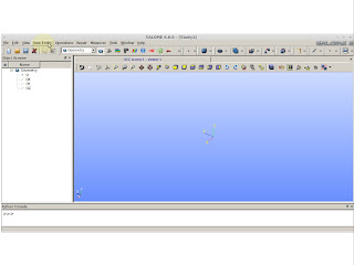
Turn Salomé On and choose Geometry.
Inside the yellow circle.
Go to "New Entity"
New Entity >> Basic >> Point
Here you'll put the values from the measurements we have. At this point we are placing the value of OD_max divided by 2. I'm using radial symmetry that is why we must divide. For this point, and for the subsequent, we will use a reference. So, for this case we are using the reference "O" (origin).
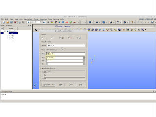
Pay attention on the selection
On the next picture we can see we changed the reference point. This reference point is the same that was created on the previous picture. This action is to make the point to walk 0.3 meters on the "y" axis. This value came from the half of the WaC.
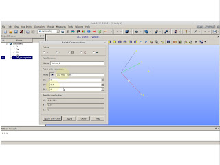
OD_max_point (the one was created) is now our reference.
Now we will take the previous point as reference again and making him walk SmSpa in "y" axis and also walk -0.0254 m  on the "x" axis. 0.0254 is the difference between the OD values. Remember, our point was on the OD_max and by reducing it in 0.0254 we will place the point in OD_min.
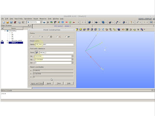
Creating the small space and the OD_min_point
Now we have to create the point for the end of the fishing neck.
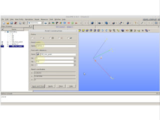
Creating FN point
Now we changed the point creation approach. It is not referenced anymore. By having the displacement into the "y" axis for the last point creations you will see we placed the last point at (OD_min/2 , SmSpa+Wac/2+FN,0). We only want the value SmSpa+Wac/2+FN because the next point will be (0,SmSpa+Wac/2+FN,0).
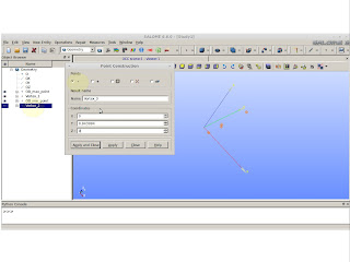
The value on the "y" is just SmSpa+Wac/2+FN
Now we must connect all those dots by creating lines. Create the lines by following the dot creation sequence. Remember to using the origin "O", or else you would have an opened figure. We don't want that.
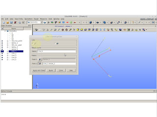
New Entity >> Basic >> Lines
We should have created 6 lines. Press "Ctrl" and select every single created line.
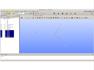
Selecting all the lines
To have a surface we must create a wire from the those selected lines.
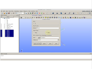
New  Entity >> Build >> Wire

From the created wire we must create a face.
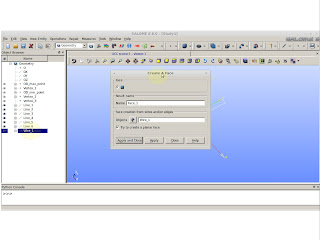
New Entity >> Build >> Face
Now is time to see something solid. We will create the solid by rotating the face we just created. This revolution will occur on the "y" axis.
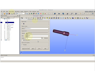
New Entity >> Generation >> Revolution
Now, we have the stabilizer basis from this point we must create a way of cutting the spiral blades. You must be asking: "Why are we not creating the spiral blades on the top of the minor OD?". Mainly, because, by doing this way we can create some areas of undesired edges and when we create a mesh from this subject, the mesh will be faulty.  

To create the blades, I know, from self experience, the spiral will have the following set of parametric equations (0.5*OD*cos(t+pi/2), 0.5*OD*sin(t+pi/2), t*1.2/pi). The OD value can be OD_max or OD_min. For the OD_max I suggest, instead of using 0.5 as the first multiplier, use 0.6. If you do use 0.5 you might find problems later. So ... for OD_max use 0.6.
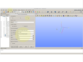
New Entity >> Basic >> Curve
From the previous picture you will see I shot my feet twice I didn't use the recommendation I gave you. Up their in the front I had issues. The second shot is the value in the Max t (check above picture) this value "t" should be equal to (WaC/2+ SmSpa)*pi/1.2 rounded to the bigger value. If you use a minor value you will have a "shitty" blade.

Now, do this for OD_min as well and you will have two spiral curves!!!

After creating these curves we must proceed as we did before. Create a wire from these 2 curves. To do this we need to explode both curves into vertexes.
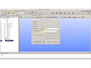
New Entity >> Explode. Pay attention to choose Sub-shape as Vertex
We must connect the exploded vertexes with lines. Connect the opposite vertexes so you´ll have a closed shape and then we can create the wire.
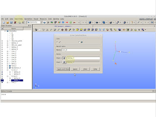
Connecting opposite vertexes
We have 2 lines and two curves. "Ctrl" select them and create a wire.
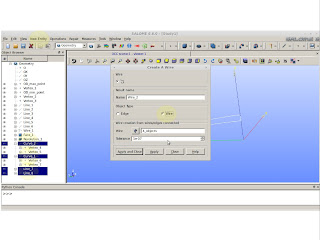
Creating a wire from the selected lines and curves
So ... to create a solid from a wire, we just need two more steps: create a face and revolution it also.
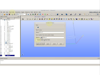
For this case we don't want to create a planar face. "Untoggle" it. 
Construct by revolving the face. We will rotate only 80 degrees. Don't ask. It is based on experience.
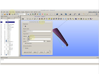
Solid cutting tool
We should have 2 solids and we need to cut the last created solid over the first one.
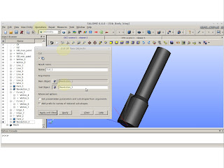
Operations >> Boolean >> Cut
As a result we should see something like this: 
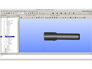
Result
From the back experience I have, it is fail safe to rotate the bigger solid. This is mainly because of the high tortuosity created by the spiral curve. If you rotate the spiral cutting tool, you might have issues when generating the mesh.
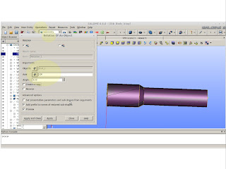
Operations >> Transformation >> Rotation
Do this rotation and cut 2 times and you should have as a result the following solid:
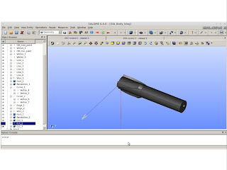
Half of stabilizer body
After this whole trouble we are only on the half of the way. F%&$##

Just kidding.

Lets make a mirror image.
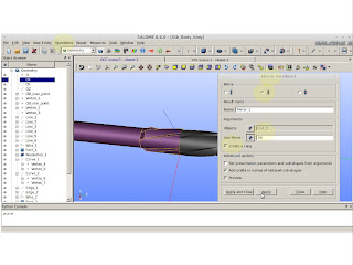
Operations >> Transformation >> Mirror Image
You will see the stabilizer is crooked. By my expectations we should need to rotate the mirrored image 20 degrees.
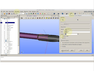
Correction
Now it is time for the super bonder. Fuse both halfs to make a whole.
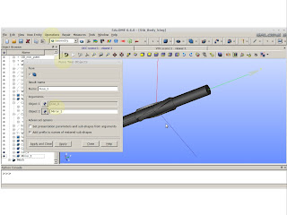
Operation >> Boolean >> Fuse
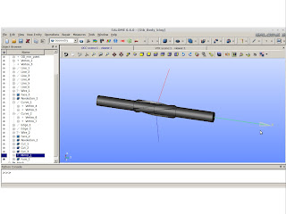
I believe we are done.
Useful stabilizer to be used as a mesh basis
If you have any doubt. Feel free to send me an email.

On the next posting I'll evaluate the Python script from this creation.

PS: This is not the easiest way of creating a stabilizer, but it is a fail safe creation for meshes.


quinta-feira, 11 de abril de 2013

Creating a spiral drilling stabilizer with Salomé - Presenting

I'm going to need from you a very brief knowledge of Salomé. I would suggest you to download the explanatory videos from this website http://www.caelinux.org/wiki/index.php/Doc:Salome it is a little outdated but it's going to help you a lot if you don't know a thing about Salomé.

  • What will we be drawing?
  • Why are we going to draw a spiral stabilizer?
  • What is this for?
What will we be drawing? 

We will draw a drilling stabilizer. In the drilling industry we have several types of drilling stabilizers:

  • Straight Integral Blade Stabilizers;
  • Straight Welded;
  • Spiral Integral;
  • Spiral Welded;
  • Sleeve Blade;
  • Variable OD - its size can vary accordingly;
  • Etc ...

Several types of drilling stabilizer. Extracted from the web @ http://dns.tix.co.jp/eng/products_tsk/drilling.html


Why are we going to draw a spiral stabilizer? 


Because it is a simple tool but it has a complex spiral design and if we learn a way of doing it, we basically can draw whatever we may want. Of course, from my point of view!!


    What is this for?


    These devices are used ... well ... to stabilize the BHA in the hole and to improve or reduce the "building" capability of the BHA.

    BHA stands for Bottom Hole Assembly. It is a combination of tools to drill a well. The basic design is drilling bit, drill collars and heavy weight drill pipes.

    Example of a simple BHA. Bit+Drill Collar+Stb+DC's and HWDP


    Identifying the steps and the tools to be taken into account

    Taking into account what I had explained already we need to "divide to conquer". So, to help us on this task we will need:

    1. Identify the problem ( this is going to be done recursively)
      1. Understand the physics behind.
      2. Search for previous papers.
      3. What is different from previous works?
      4. Where can be applied the acquired knowledge?
      5. ...
    2. Salomé
      1. It can create meshes.
      2. You can name all the faces, patches, vertices easily.
      3. Accept scripts (python).
      4. It is FREE!!!!
    3. Openfoam
      1. It is well known software.
      2. You can learn C++.
      3. It is supposed to be easy ... well ... not all true.
      4. It is FREE!!!!
    4. Linux
      1. If you have a multicore processor, you can divide the task.
      2. It has a huge amount of libraries and mathematical tools.
      3. It is FREE!!!!

    Hands On!!!

    I'll post another picture from one the several beaches we have on the nearby areas. Just to keep a high moral.
    Pitangui


    The driver

    To make things easier and interesting, I suggest you to have a problem to be solved. In my case I would like to understand the flow behavior that happens around a drilling BHA (I will explain this later). To succeed with this I need to divide this problem in several steps so you, reader (again ... if any), can understand the basic principles of this software.

    The problem itself is not trivial and we have several publications about this subject, annular flow. So, in a simple statement, flow around a drilling BHA is a annular flow, made it simple. But the BHA itself has some very different tools on it and the most common and important tool that can change your flow pattern in the annular is the stabilizer.

    Simple spiral drilling stabilizer made with Salomé
    So, just before getting into the action we need to establish which steps we will be taking and the order of them.

    Who am I?

    My name is Rafael and I have the luck to live on a very nice city, Natal-RN. This sunny and touristic place has its own advantages and a set of disadvantages as well. I'm a engineer and here we can't find courses related to my area and that is one of the main reasons I'm writing this text - self learning.

    Due to this lack of course offering I need to extract most of the knowledge from the web.  Which lead me the following fact - I'm terrible with my own reports ... I'm good with reports that I need to deliver ... mine ... just terrible. The "reporting behavior" is good because you don't need to keep learning the same subject several times. If you have a previous report, just read it and refresh your memory. As I said, I'm terrible with that.

    The second reason from this blog is to help others. I will try to make things easier regarding learning Openfoam. I'll follow a very didactic approach so you, reader (if any), reach or improve your self development level as well.

    Natal-RN - The best city in Brazil.