What I usually like to do with Salomé is draw the tool I want and after that, create a dump file so I can "steal" the Python coding and work on it after.
First things first.
The model:
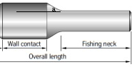
This is a "virgin" unfinished stabilizer, so the manufacturer can cut it in any quantity of blades or shapes he may want. We will work over this type of shape. As you can see, it has two main outside diameters (OD max and OD min) and for the problem I want to solve I will set the following values for the lengths and for the OD's:
- Bottom Neck=0.6 meters
- Fishing Neck=0.6 meters
- Wall Contact=0.6 meters
- OD_max=0.2159 meters
- OD_min=0.1651 meters
Just to make things easy.
But, we are missing a small space between the Fishing Neck (FN) and Wall Contact (WaC). We will call it Small Space (SmSpa). And this should be calculated taking into account the angle formed between the end of the FN and beginning of the WaC.
 |
| Showing the angle a between FN and WaC. |
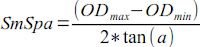
- a=30 degrees
Salomé
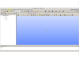
Turn Salomé On and choose Geometry.
 |
| Inside the yellow circle. |
Go to "New Entity"
 |
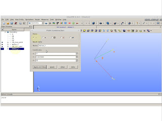
| New Entity >> Basic >> Point |
Here you'll put the values from the measurements we have. At this point we are placing the value of OD_max divided by 2. I'm using radial symmetry that is why we must divide. For this point, and for the subsequent, we will use a reference. So, for this case we are using the reference "O" (origin).
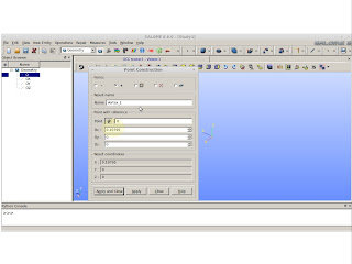 |
| Pay attention on the selection |
On the next picture we can see we changed the reference point. This reference point is the same that was created on the previous picture. This action is to make the point to walk 0.3 meters on the "y" axis. This value came from the half of the WaC.
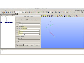 |
| OD_max_point (the one was created) is now our reference. |
Now we will take the previous point as reference again and making him walk SmSpa in "y" axis and also walk -0.0254 m on the "x" axis. 0.0254 is the difference between the OD values. Remember, our point was on the OD_max and by reducing it in 0.0254 we will place the point in OD_min.
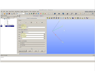 |
| Creating the small space and the OD_min_point |
Now we have to create the point for the end of the fishing neck.
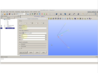 |
| Creating FN point |
Now we changed the point creation approach. It is not referenced anymore. By having the displacement into the "y" axis for the last point creations you will see we placed the last point at (OD_min/2 , SmSpa+Wac/2+FN,0). We only want the value SmSpa+Wac/2+FN because the next point will be (0,SmSpa+Wac/2+FN,0).
 |
| The value on the "y" is just SmSpa+Wac/2+FN |
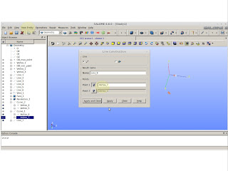
Now we must connect all those dots by creating lines. Create the lines by following the dot creation sequence. Remember to using the origin "O", or else you would have an opened figure. We don't want that.
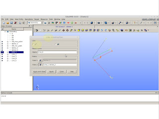 |
| New Entity >> Basic >> Lines |
We should have created 6 lines. Press "Ctrl" and select every single created line.
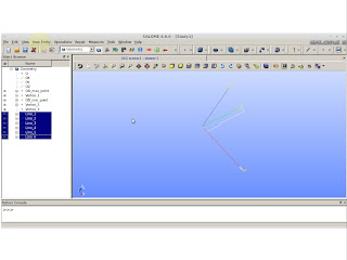 |
| Selecting all the lines |
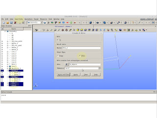
To have a surface we must create a wire from the those selected lines.
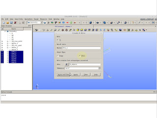 |
| New Entity >> Build >> Wire |
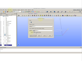
From the created wire we must create a face.
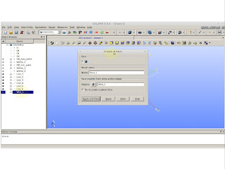 |
| New Entity >> Build >> Face |
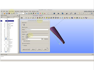
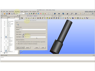
Now is time to see something solid. We will create the solid by rotating the face we just created. This revolution will occur on the "y" axis.
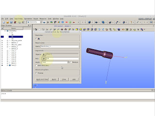 |
| New Entity >> Generation >> Revolution |
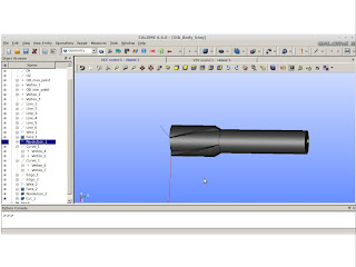
Now, we have the stabilizer basis from this point we must create a way of cutting the spiral blades. You must be asking: "Why are we not creating the spiral blades on the top of the minor OD?". Mainly, because, by doing this way we can create some areas of undesired edges and when we create a mesh from this subject, the mesh will be faulty.
To create the blades, I know, from self experience, the spiral will have the following set of parametric equations (0.5*OD*cos(t+pi/2), 0.5*OD*sin(t+pi/2), t*1.2/pi). The OD value can be OD_max or OD_min. For the OD_max I suggest, instead of using 0.5 as the first multiplier, use 0.6. If you do use 0.5 you might find problems later. So ... for OD_max use 0.6.
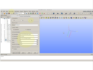 |
| New Entity >> Basic >> Curve |
From the previous picture you will see I shot my feet twice I didn't use the recommendation I gave you. Up their in the front I had issues. The second shot is the value in the Max t (check above picture) this value "t" should be equal to (WaC/2+ SmSpa)*pi/1.2 rounded to the bigger value. If you use a minor value you will have a "shitty" blade.
Now, do this for OD_min as well and you will have two spiral curves!!!
After creating these curves we must proceed as we did before. Create a wire from these 2 curves. To do this we need to explode both curves into vertexes.
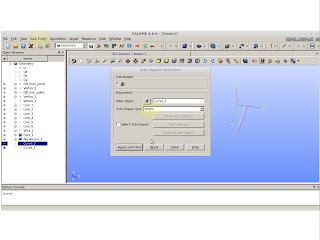 |
| New Entity >> Explode. Pay attention to choose Sub-shape as Vertex |
We must connect the exploded vertexes with lines. Connect the opposite vertexes so you´ll have a closed shape and then we can create the wire.
 |
| Connecting opposite vertexes |
We have 2 lines and two curves. "Ctrl" select them and create a wire.
 |
| Creating a wire from the selected lines and curves |
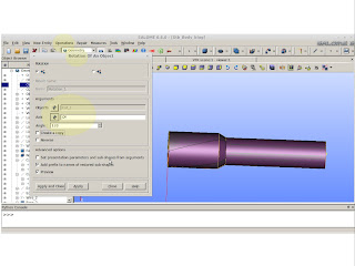
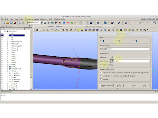
So ... to create a solid from a wire, we just need two more steps: create a face and revolution it also.
 |
| For this case we don't want to create a planar face. "Untoggle" it. |
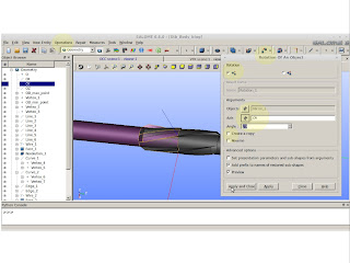
Construct by revolving the face. We will rotate only 80 degrees. Don't ask. It is based on experience.
 |
| Solid cutting tool |
We should have 2 solids and we need to cut the last created solid over the first one.
 |
| Operations >> Boolean >> Cut |
As a result we should see something like this:
 |
| Result |
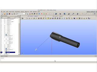
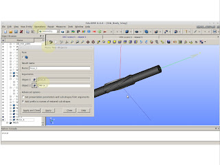
From the back experience I have, it is fail safe to rotate the bigger solid. This is mainly because of the high tortuosity created by the spiral curve. If you rotate the spiral cutting tool, you might have issues when generating the mesh.
 |
| Operations >> Transformation >> Rotation |
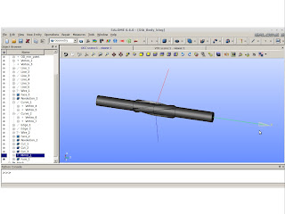
Do this rotation and cut 2 times and you should have as a result the following solid:
 |
| Half of stabilizer body |
After this whole trouble we are only on the half of the way. F%&$##
Just kidding.
Lets make a mirror image.
 |
| Operations >> Transformation >> Mirror Image |
You will see the stabilizer is crooked. By my expectations we should need to rotate the mirrored image 20 degrees.
 |
| Correction |
Now it is time for the super bonder. Fuse both halfs to make a whole.
 |
| Operation >> Boolean >> Fuse |
I believe we are done.
 |
| Useful stabilizer to be used as a mesh basis |
If you have any doubt. Feel free to send me an email.
On the next posting I'll evaluate the Python script from this creation.
PS: This is not the easiest way of creating a stabilizer, but it is a fail safe creation for meshes.


Nenhum comentário:
Postar um comentário